Conversation
dlharmon
approved these changes
May 22, 2021
Collaborator
 dlharmon
left a comment
dlharmon
left a comment
There was a problem hiding this comment.
I expect this will perform as desired.
C68 and C69 would probably be better as 220 pF. This would provide the same transfer function for the feedback network as in Table 1 of the AP3441 data sheet. Alternately, the resistor values could be increased by a factor of 10 to match the data sheet. Realistically, it should work fine with 22 pF or even no part populated.
Pin 3 of the AP3441 is the power input to the switch, pin 7 is just an enable. Input capacitor placement could be closer to pin 3. I expect it to work properly given the wide plane area and thin dielectric to the ground plane. EMI may be slightly increased over optimal capacitor placement.
This file contains hidden or bidirectional Unicode text that may be interpreted or compiled differently than what appears below. To review, open the file in an editor that reveals hidden Unicode characters.
Learn more about bidirectional Unicode characters
Sign up for free
to join this conversation on GitHub.
Already have an account?
Sign in to comment
2 participants
Add this suggestion to a batch that can be applied as a single commit.This suggestion is invalid because no changes were made to the code.Suggestions cannot be applied while the pull request is closed.Suggestions cannot be applied while viewing a subset of changes.Only one suggestion per line can be applied in a batch.Add this suggestion to a batch that can be applied as a single commit.Applying suggestions on deleted lines is not supported.You must change the existing code in this line in order to create a valid suggestion.Outdated suggestions cannot be applied.This suggestion has been applied or marked resolved.Suggestions cannot be applied from pending reviews.Suggestions cannot be applied on multi-line comments.Suggestions cannot be applied while the pull request is queued to merge.Suggestion cannot be applied right now. Please check back later.
All of the work is constrained to the area shown here:
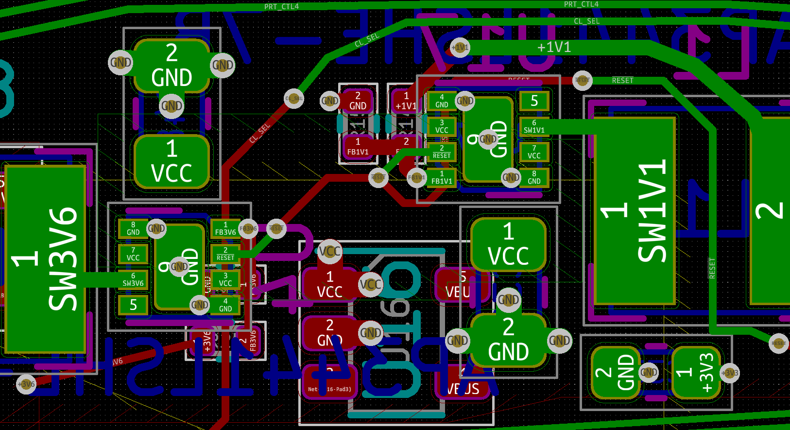
I tried really hard to minimize fill cuts. I need help checking that I have done ground vias properly on U4 and U17, that the VCC area is sufficient for expected power, and anything else that would be affected by modifying that area. I don't see any high speed traces that have changed, or fills underneath them. So most of my concern is with power stability.